Author: Time:2024-08-15
Principle of amplitude grating
An optical element composed of a large number
(thousands or even tens of thousands) of slits of equal width and spacing is
called a diffraction grating. However, there are already many types of modern
gratings, and some diffraction units of gratings are no longer narrow slits in
the usual sense. In order to include the definition of diffraction gratings in
these gratings, gratings are defined as optical elements that can produce
periodic spatial modulation of the amplitude or phase of incident light, or
both simultaneously. Grating can be classified into amplitude grating and phase
grating based on the modulation of its incident light.
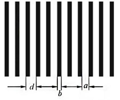
Overview
diagram of amplitude grating
The multi slit Fraunhofer diffraction device
includes a diffraction screen. The diffraction screen has many slits of equal
width and spacing, with a slit width of and a spacing of d. It can modulate the
amplitude of incident light spatially and periodically. This type of
diffraction screen is also known as an amplitude type rectangular grating, with
d referred to as the grating constant.
An amplitude grating is a device that can modulate
the amplitude of incident light waves according to the laws of sine or cosine
functions, without affecting the phase distribution. The complex amplitude
transmission coefficient is given by the following formula.

This is a 1D grating that is infinitely long in the
x direction and has a certain B range. B represents the modulation amplitude of
the grating on the amplitude of the light wave, and d is the grating constant.
This grating can be obtained by capturing the interference fringes of two plane
waves at a certain angle in the propagation direction. As shown in the figure,
the complex amplitude transmission coefficients of sine grating and rectangular
amplitude grating are displayed.
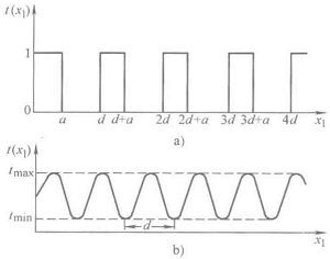
Intensity distribution of amplitude grating
Assuming a sine grating contains N interference
fringes with a spacing of d. So, when a monochromatic plane wave with unit
amplitude vertically illuminates a grating, the amplitude distribution on the
plane immediately behind the grating can be written as (assuming the grating
transmission coefficient varies along the x1 direction)

Among them, the above equation represents within the
grating range, the following equation represents outside the grating range, and
B is a constant less than 1.
Calculate the diffraction intensity distribution of
a grating with N units (each stripe can be regarded as a diffraction unit).
Just need to obtain the diffraction factor of the unit, and then multiply it by
the multi beam interference factor to obtain it. For the sinusoidal grating
under discussion, the complex amplitude generated by unit diffraction is
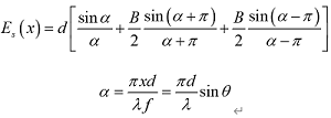
PS. Multi beam interference factor is ,
,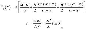 and β is the wavelength of light waves.
So, the intensity distribution of the sinusoidal
grating diffraction pattern is
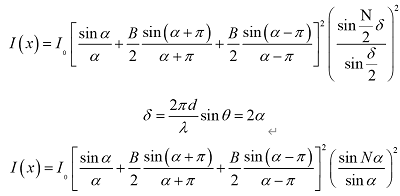
Note the formula , the above equation can also be written as
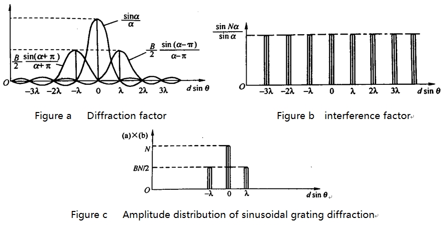
In the formula, the diffraction intensity of the
unit includes a large number of terms, making it difficult to accurately draw
its image. Only their amplitude distribution diagrams are shown in Figures a to
c. Figures a and b belong to diffraction factors and interference factors,
respectively, and Figure c is their product. It can be seen that the diffraction
pattern of the sine grating only contains zero order and ±1st order spectral lines. Similarly, the broadband of spectral lines
is inversely proportional to the number of periods N of the grating. When N
approaches infinity, the spectral line width decreases to zero, which can be
mathematically represented by three delta functions.
previous:Various manufacturing standards, Resolution targets
Next:High damage threshold but only measure 1Hz lasers, Laser energy meter
Product Navigation : Microlens Array Off axis
link : Sina Blog Alibaba163 Blog
Copyright: Highlight Optics Co., Ltd. Address:4A150 No.1 Trading Plaza, China South City, Longgang District, Shenzhen, China
Phone: 0086 0755 89319011 Email: sales@highlightoptics.com